Now that everything is setup, in this tutorial we will be blinking the onboard LED on the PIC32.
DISCLAIMER:
I am going to assume you know basic C before beginning this tutorial, if not this website should help.
Setup
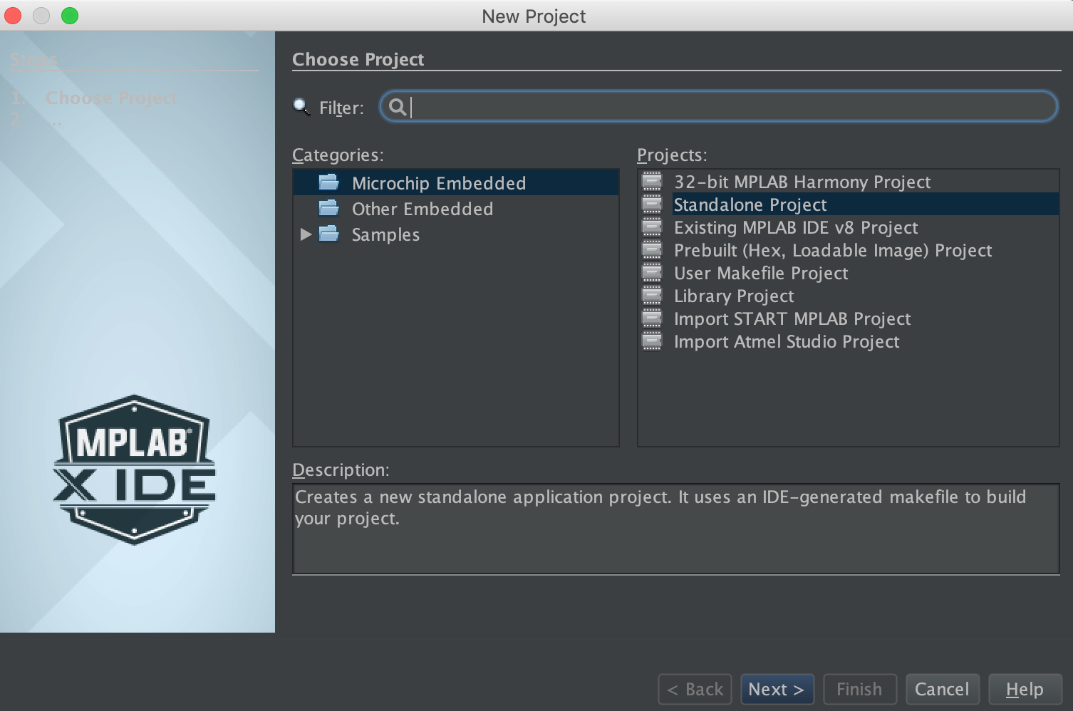
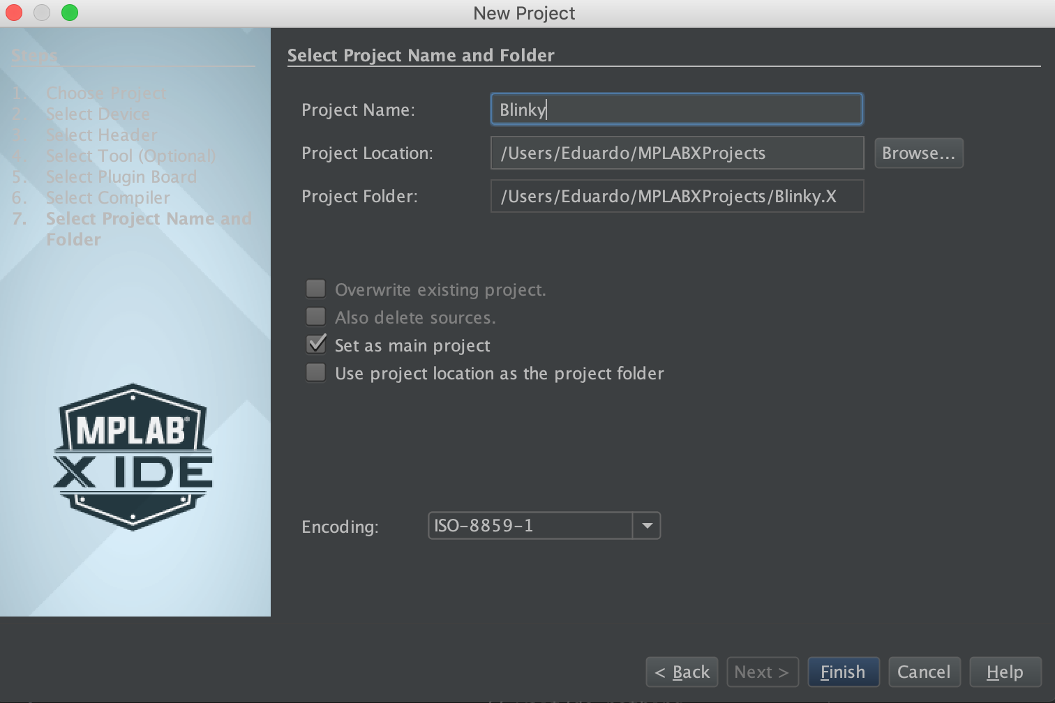

Configuration
Before we right any code, it is important we write the settings for the PIC32MK1024GPE100. To do that we have to set registers called Configuration bits.
Looking at the PIC32MK family datasheet on (Page 9), we see a section called Special Features on (Page 589). This section gives us a lot of info about how to set the configurations for the PIC32. A register is just a memory location in the MCU, that has bits, in this case 32 bits since were using the PIC32, that can be "set" or "off" in order to perform a wide variety of functions. In this case we are using these registers to set configuration bits, or various settings for the MCU, such as the system clock frequency, and whether JTAG is enabled. As shown below the PIC32 uses a lot of Device configuration Registers, each contained in one 32 bit word. For this project we will only be dealing with Device Configuration Words 0-3, as those contain a majority of the settings we need for this project
• DEVSIGN0:DeviceSignatureWord0Register
• DEVCP0: DeviceC ode- Protect 0 Register
• DEVCFG0: Device Configuration Word 0
• DEVCFG1: Device Configuration Word 1
• DEVCFG2: Device Configuration Word 2
• DEVCFG3: Device Configuration Word 3
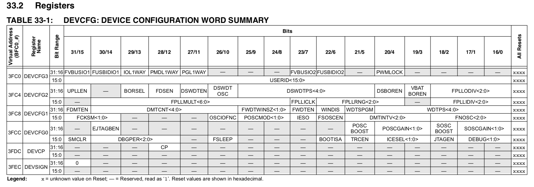
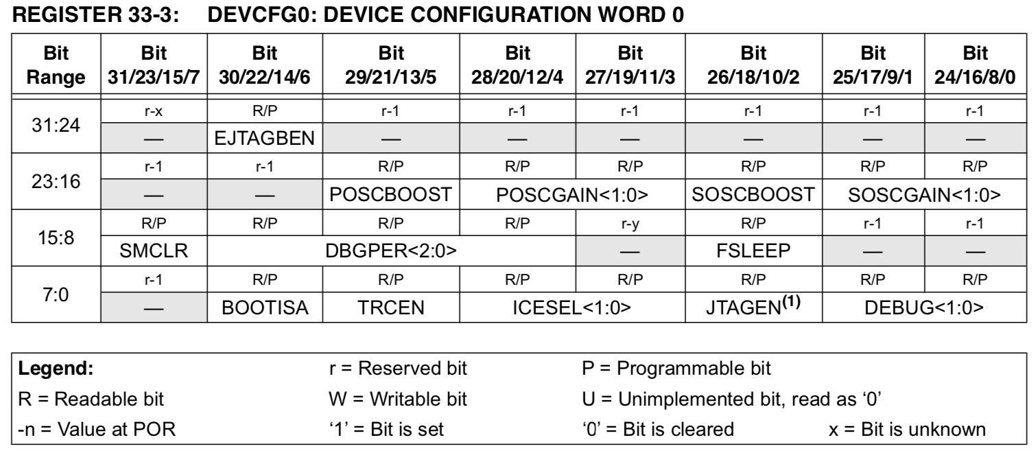
As you can see on page 590, each device configuration register is 32 bits long, each has a unique memory location, and unique bit ranges that perform specific functions when set. If we go to page 594, we see all the layout for Device Configuration Word 0, and below the datasheet tells us what setting is triggered when specific bits of the 32 bit word is "cleared", or "set". Not all bits are used as can be seen in register DEVCFG3
The easiest way to configure these settings is to go to Window->Target Memory Views-> Configuration Bits
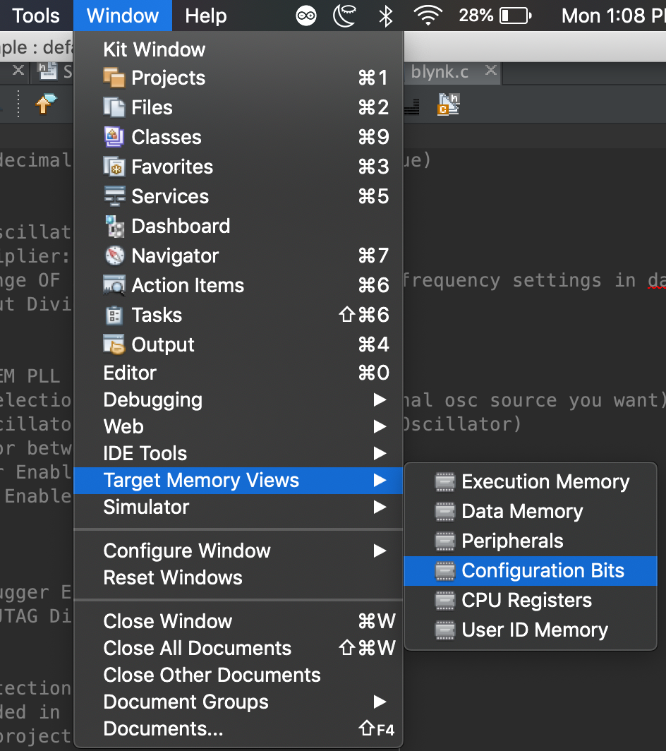 This opens up a GUI that allows you to individually set all the configuration bits related to the device you selected. We will not be setting all these bits, only a few we need for this particular project. Information on all the configuration bits can of course be found in the datasheet pages 594-602.
// DEVCFG3
#pragma config USERID = 0xFFFF // Enter Hexadecimal value (Enter Hexadecimal value)

// DEVCFG2
#pragma config FPLLICLK=PLL_FRC // Primary oscillator is input to PLL
#pragma config FPLLMULT = MUL_80 // PLL Multiplier: 8MHz Multiply by 8*80=640MHz
//Output to FPLLODIV needs to be within a range OF 350 MHZ and 700 MHz check EC frequency settings in datasheet
#pragma config FPLLODIV = DIV_16 // PLL Output Divider: 640MHz/16=40Mhz=SYSCLK

// DEVCFG1
#pragma config FPLLRNG=RANGE_5_10_MHZ //SYSTEM PLL INPUT RANGE 5-10 MHZ
#pragma config FNOSC = SPLL  // Oscillator Selection Bits (8Mhz)(Select which final osc source you want)
#pragma config FSOSCEN = OFF // Secondary Oscillator Disabled (Enable Secondary Oscillator)
#pragma config POSCMOD = OFF // Use oscillator between osc1 and osc2
#pragma config FWDTEN = OFF // Watchdog Timer Enable (WDT Disabled)
#pragma config FDMTEN = OFF // Deadman Timer Enable (Deadman Timer is disabled)


// DEVCFG0
#pragma config DEBUG = OFF // Background Debugger Enable (Debugger is disabled)
#pragma config JTAGEN = OFF // JTAG Enable (JTAG Disabled)

// DEVCP
#pragma config CP = OFF // Code Protect (Protection Disabled)
// #pragma config statements should be included in .c file
// #pragma config statements should precede project file includes.
// Use project enums instead of #define for ON and OFF.
Setting a configuration bit is done with the directive pragma, followed by config for configuration.